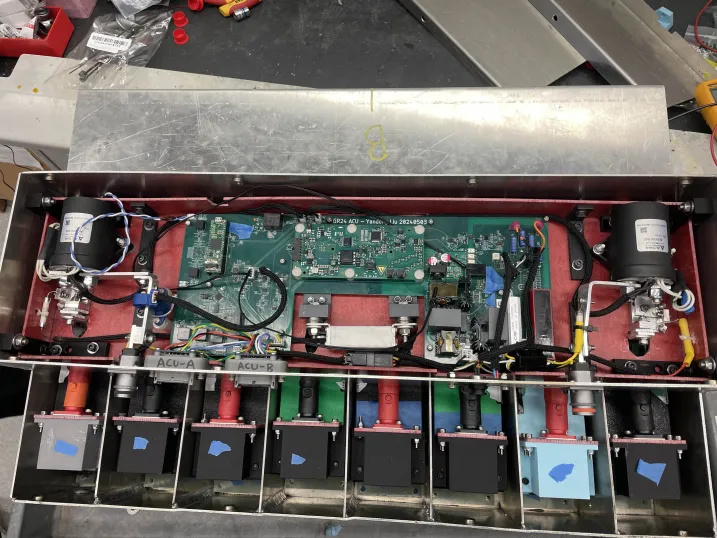
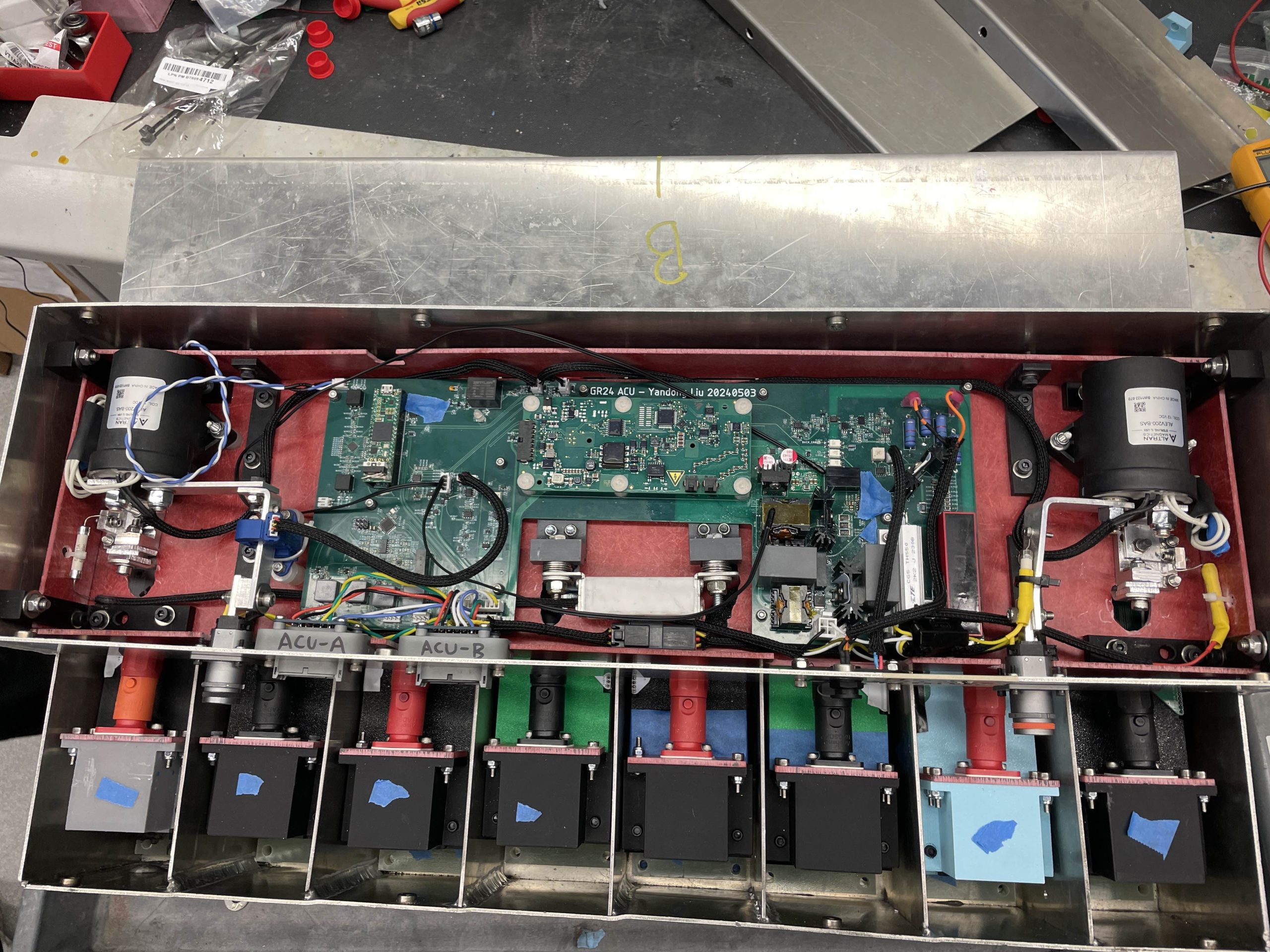
Electrical Architecture
Key Rule Requirements
- Max total battery voltage – 600V (EV3.3)
- Max power output – 80kW (EV3.3)
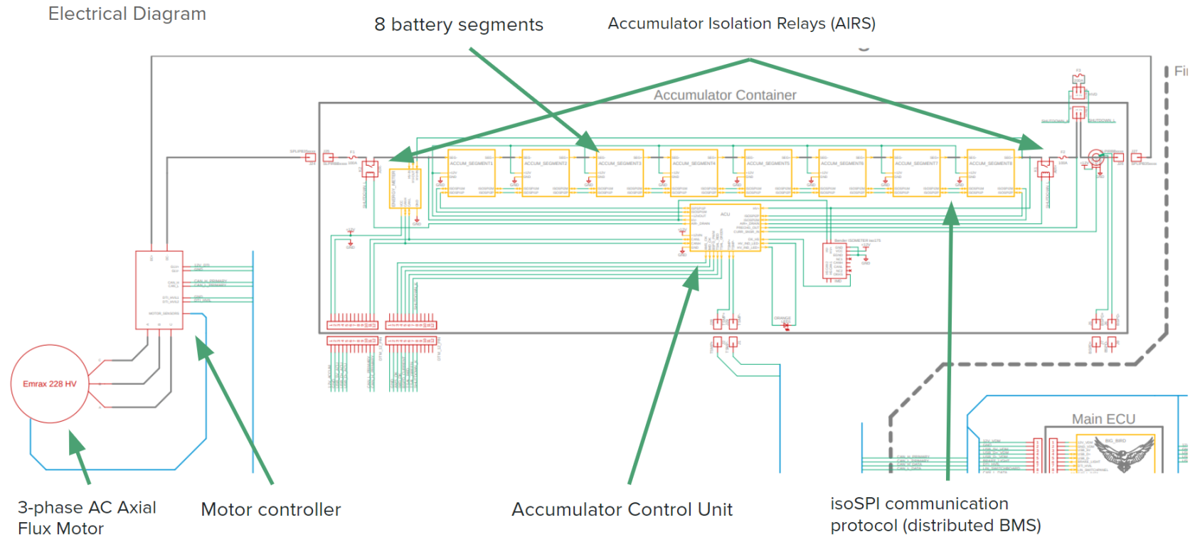
- Two NO AIRs (accumulator isolation relays) on each accumulator pole
- Precharge & discharge circuit to limit TS inrush current and discharge capacitors (EV5.6)
- TS galvanically isolated from GLV (EV6.5)
- Shutdown circuit drives one AIR (EV7.1)
Design Decisions:
- Cylindrical 2170 cells
- Distributed BMS system
- 128s3p architecture
- Max battery voltage – 537.6V
- Max power output – 72.6kW
- Nominal energy capacity – 6.2 kWh
- Power exceeding 60kW not shown to have distinguishable improved placements in dynamic events (EVW)
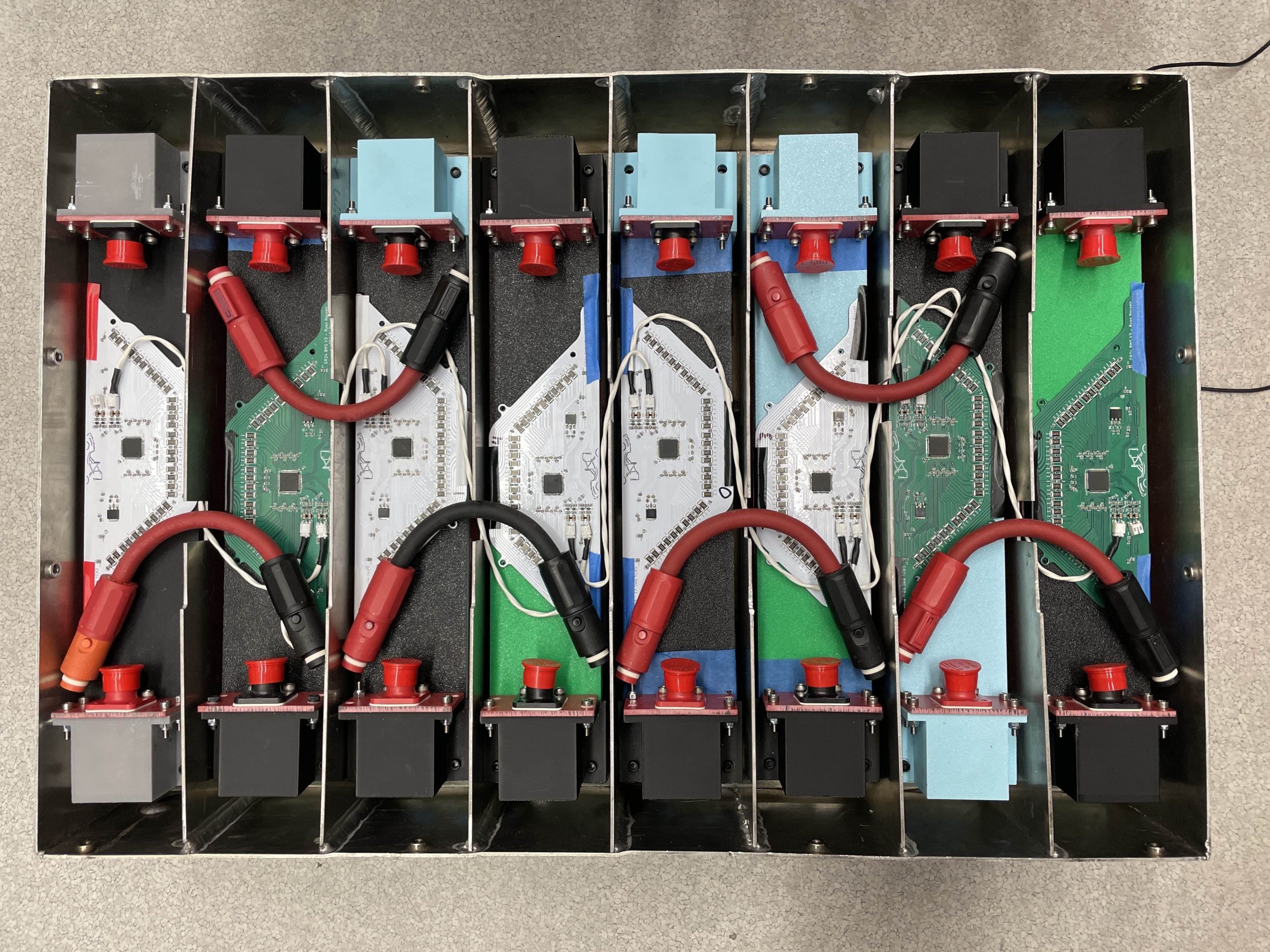
- Split into 8 segments in series
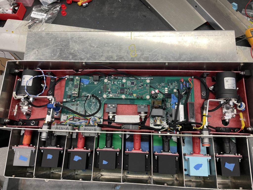
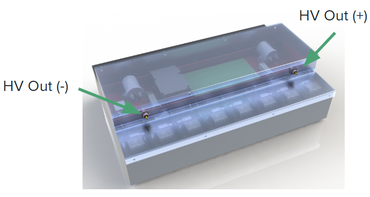
- ACU (Accumulator Control Unit) contains all logic circuitry within accumulator
- Controls relays, fans, lights
- Contains precharge/discharge circuit
- Contains BMS main board
Battery Fusing
Power Loads
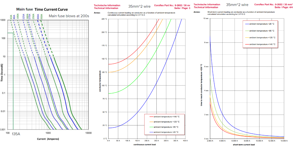
- 135A max current (6 seconds during acceleration event)
- 55A Continuous RMS Current (150 seconds during autocross)
Design Decisions:
- 63A main fuse (we want this to blow first)
- 35mm^2 / 2 gauge wire
- Bend radius is 43mm (½ distance between segments) in design, which is 4 times 11mm (wire OD). This is less than the recommended 8 times wire OD so need to keep an eye on cable kink, strain, and wear
- 8mm SURLOK connectors
Fusible Links:
Motivation – Why Wire Bonding?
- No heat interaction with Lithium
- Compared to spot welding
- Integrated fusing (details in following slide)
- Reduced contact resistance
- Quick and safe automated process
- Quality Control (Hesse Mechatronics)
Requirements
- Wire bonds rated for max of 1.75x Max cell discharge current (45A cell, 80A fuse)
- Spec from FSAE Judge
- Specify wire diameter, wire length
- Have Fast and Slow fuse blow out times (160A, 80A)
- 4N Aluminum Wire (99.99 Purity)
- Impurities change resistance
| Blow Time | |
| Current Level 1 (80A) | 30 < t < 300 sec |
| Current Level 2 | 5 sec < t < 15 sec |
| Current Level 3 | 0.2 sec < t < 1 sec |
| Current Level 4 (160A) | 0.05 sec < t < 0.15 sec |
MATLAB Simulation of 1mm Round Wire
Lumped Capacitance Model w/ Temperature Dependence:
Fuse Blowout Times for 42mm wire at various diameters
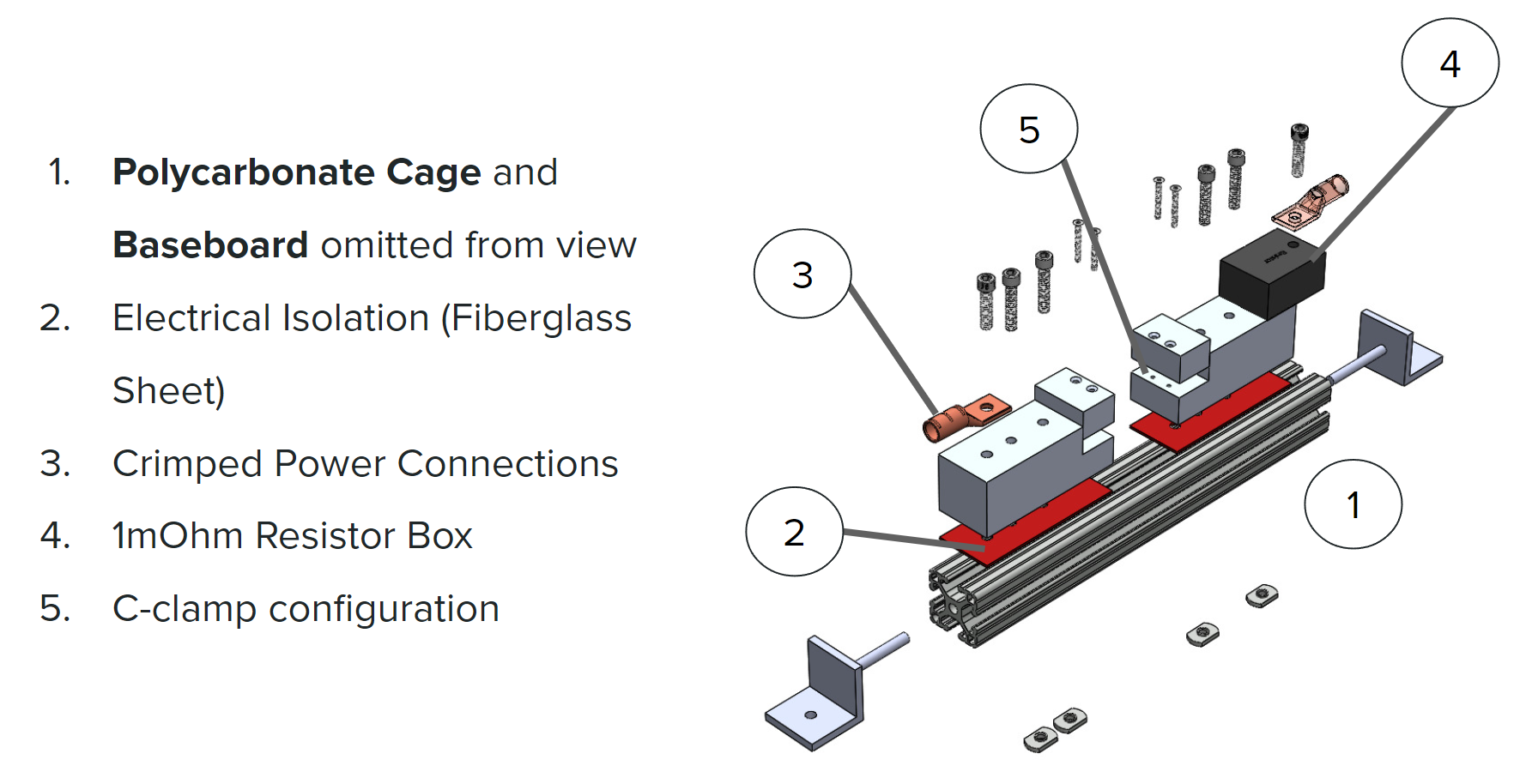
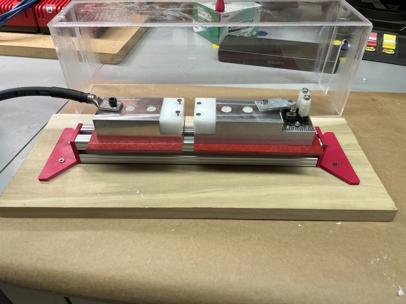
Test setup:
Battery Thermals
Simulated Power Loads for endurance event pack level adiabatic sim:
- 35kW RMS power
- 76A RMS current
- 135A peak current
Current throttled to 70%:
Battery temps increase 5°C per lap /20 laps
Transient Cell Temperature Simulation:
Assumptions
- 25°C Initial Temperature
- 40°C Coolant Temperature
- 20kW continuous pack power (2.3W each cell)
Hotspot temps w/ 60 min end condition:
Cold Plate Initial Design & Testing:
Key Design Points:
- No leak paths within of cell enclosure
- Prioritizing for now on low pressure drop
Accumulator Container
Key Rule Requirements
- Made from steel, aluminum, or composite (F10.2)
- Can be welded, fastened, or bonded (F10.2)
- Each segment separated with walls and lid (F10.3)
- 10mm holes for air flow or minimum size for cable routing (F10.4)
- Amount and size of mounts to chassis specified by accumulator weight or mount location (corner attachment) (F10.5)
- Maintenance plugs accessible immediately after opening accumulator lid and not necessary to move or remove any other components (EV5.3)
- New rule*
Design Decisions:
- Accumulator sized to fit & mount into chassis
- Experiment with welded aluminum by Neal Feay, alternative is fastened steel
- Prioritizing low tolerance for segment fitment
- Segments fastened instead of friction fit
- Second layer dimensioned to not be above maintenance plugs
Overview of Design Decisions:
- Segments fastened instead of friction fit
- Two box, three lid design allows easy access to maintenance plugs
- Adjustable mounting to account for inaccuracies in chassis fabrication
- Emphasis on ease of fabrication
- 6061 Aluminum (as per rule F.10.2)
- Box utilizes a welded (F.10.2) construction
- Welding to be done by professionals
- Prioritizing greater tolerance for segment fitment
- Lid utilizes a bent sheet metal construction
– Sized to fit and mount to the chassis
Lid Attachment:
- ¼”-20 hex head bolts + captive nuts
- Positively locked with reusable threadlocker
- Segment box lids are designed for simplest manufacturing
- Best method for accurate bends will be determined during testing phase
- Lightweight Fiber Gasket strips to prevent water infiltration
Electronics Tray
Separate compartment within accumulator that houses control electronics.
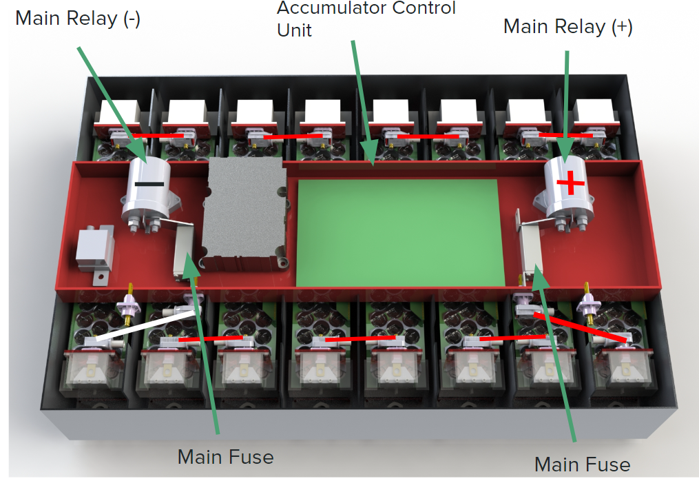
Changed to mid-pack fuse design instead of two fuses at each end:
