Key Rule Requirements
- Max segment voltage – 120V (EV5.1)
- Max segment energy – 6MJ (EV5.1)
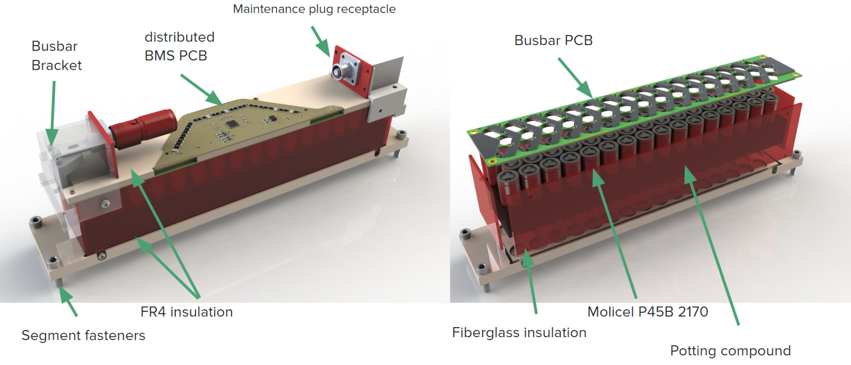
- Electrically insulated with non flammable material on top and on the side of each segment (EV5.2)
- Segments connected using positively locking, tool-less maintenance plugs (EV5.3)
- Each parallel cell needs to be fused (EV6.6)
Design Decisions:
- 16s3p segment architecture
- Each ADI BMS IC can handle 8 voltage channels
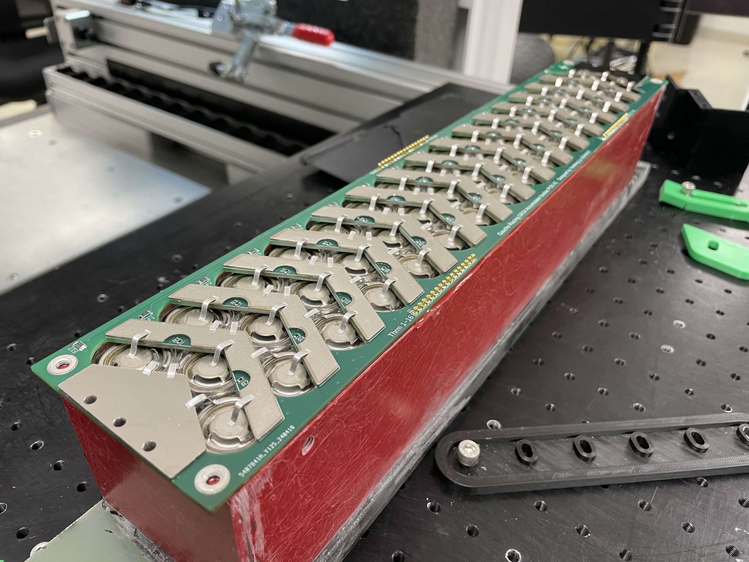
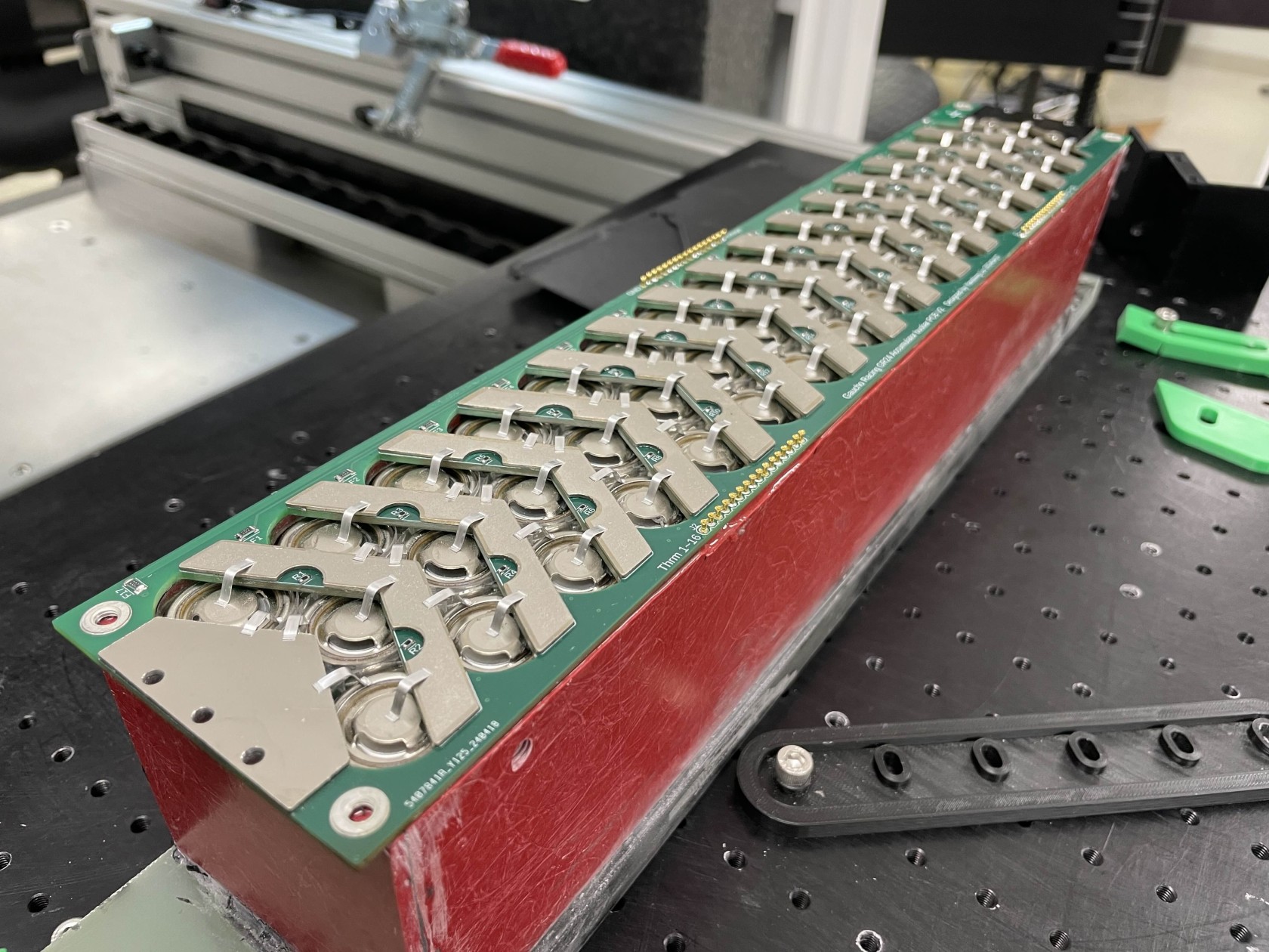
- Wire bonded fusible links for each parallel cell
- Fully CNC’d cell connections
- No cooling necessary
- Fiberglass panel insulation on the sides, kapton film insulation on top and bottom
- Cells potted with electrically insulating, thermally conductive epoxy
Fusible Links
Power Loads
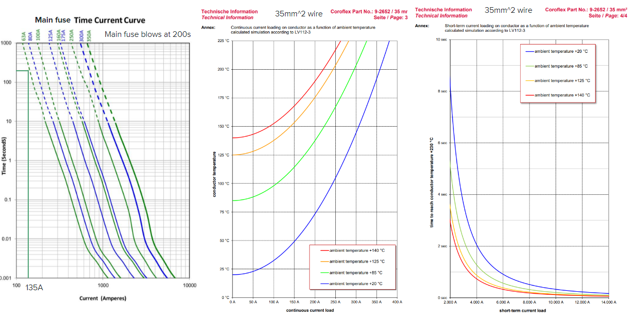
- 135A max current (6 seconds during acceleration event)
- 55A Continuous RMS Current (150 seconds during autocross)
Design Decisions:
- 63A main fuse (we want this to blow first)
- 35mm^2 / 2 gauge wire
- Bend radius is 43mm (½ distance between segments) in design, which is 4 times 11mm (wire OD). This is less than the recommended 8 times wire OD so need to keep an eye on cable kink, strain, and wear
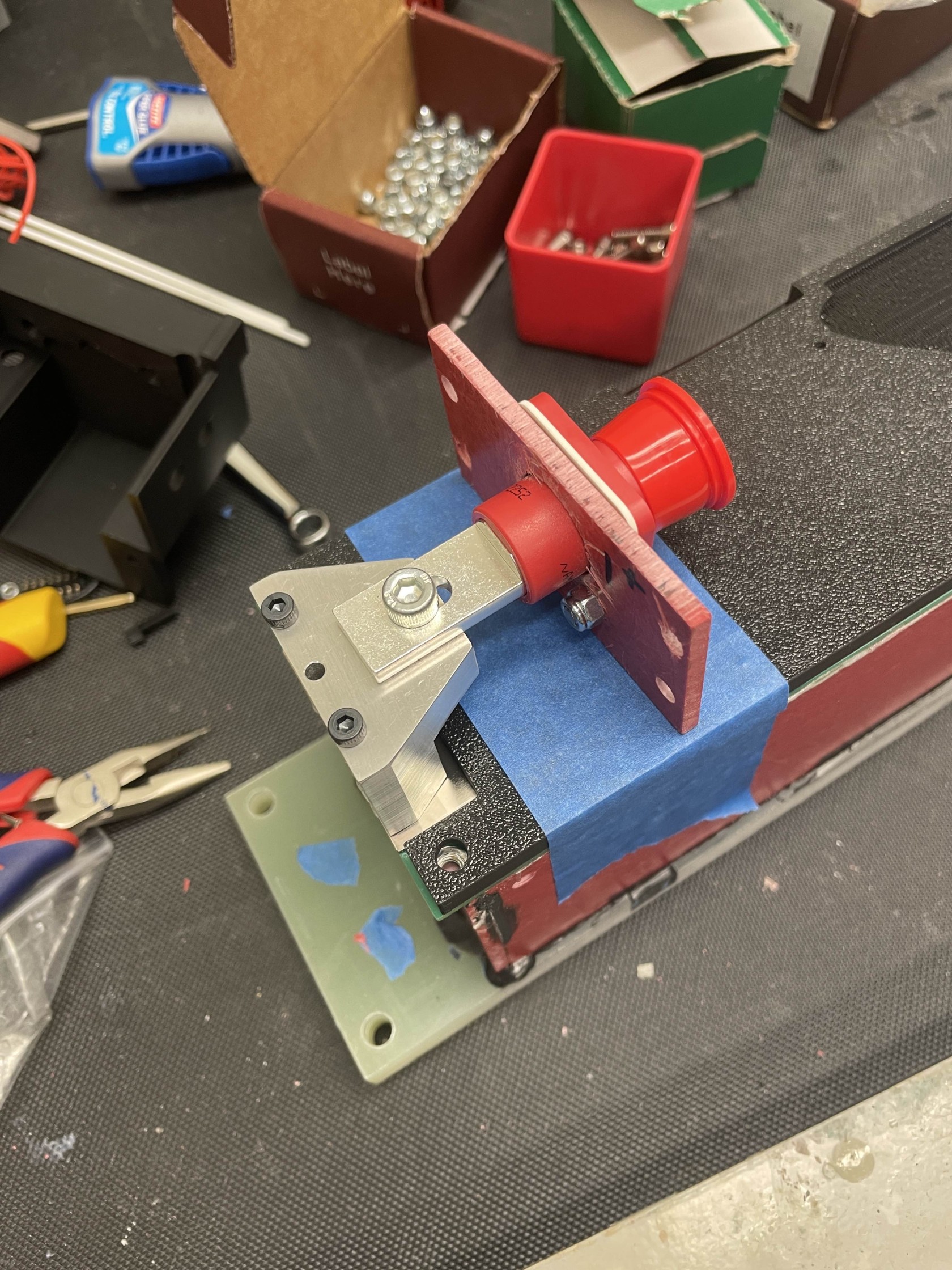
- 8mm SURLOK connectors
Fusible Links:
Motivation – Why Wire Bonding?
- No heat interaction with Lithium
- Compared to spot welding
- Integrated fusing (details in following slide)
- Reduced contact resistance
- Quick and safe automated process
- Quality Control (Hesse Mechatronics)
Requirements
- Wire bonds rated for max of 1.75x Max cell discharge current (45A cell, 80A fuse)
- Spec from FSAE Judge
- Specify wire diameter, wire length
- Have Fast and Slow fuse blow out times (160A, 80A)
- 4N Aluminum Wire (99.99 Purity)
- Impurities change resistance
| Blow Time | |
| Current Level 1 (80A) | 30 < t < 300 sec |
| Current Level 2 | 5 sec < t < 15 sec |
| Current Level 3 | 0.2 sec < t < 1 sec |
| Current Level 4 (160A) | 0.05 sec < t < 0.15 sec |
MATLAB Simulation of 1mm Round Wire
Lumped Capacitance Model w/ Temperature Dependence:
Fuse Blowout Times for 42mm wire at various diameters
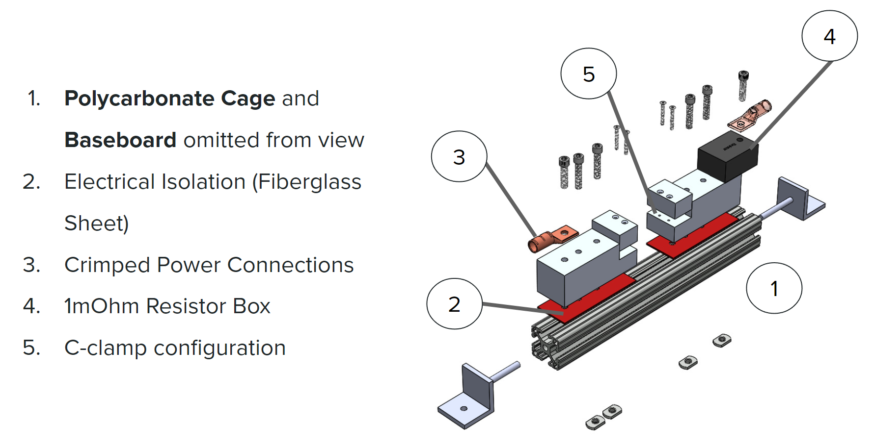
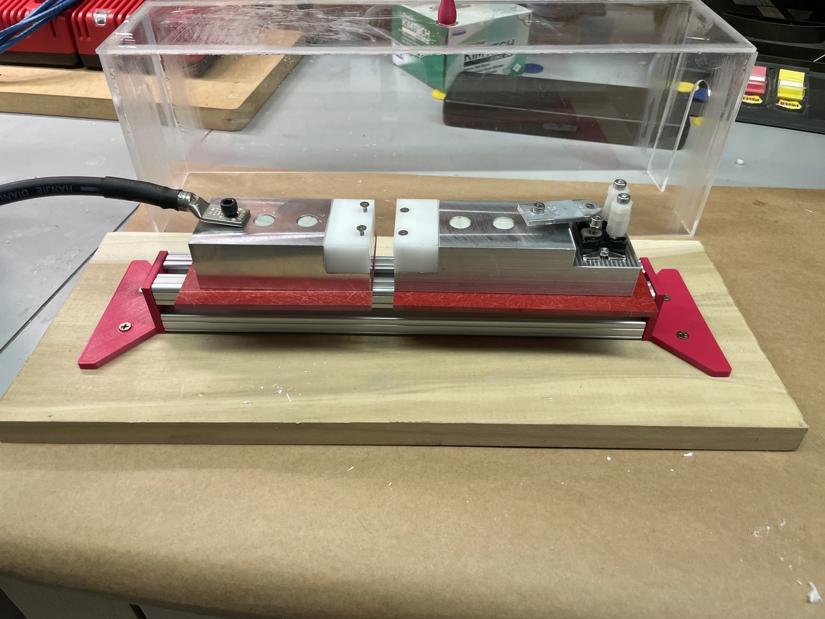
Test setup:
